Teardown of Inseego M3000B
The usb-c port in my Inseego M3000B failed this weekend. I've tried to repair it to no avail. However, I did manage to disassemble the hotspot in the process. The device uses Torx TR6 screws throughout. I don't have, nor can find anyone with, the ability to replace the USB-C port. It seems the receptacle (the pins in the middle) has cracked causing the pins to not line up correctly. The device is unable to be charged as a result. If I had an external charger for the battery I could live with it, as the back cover is easily removal--almost too easy since it falls off with the slightest bump.
This teardown probably works for the other models as well, the M3000 and M3100, as they are similar form factor.
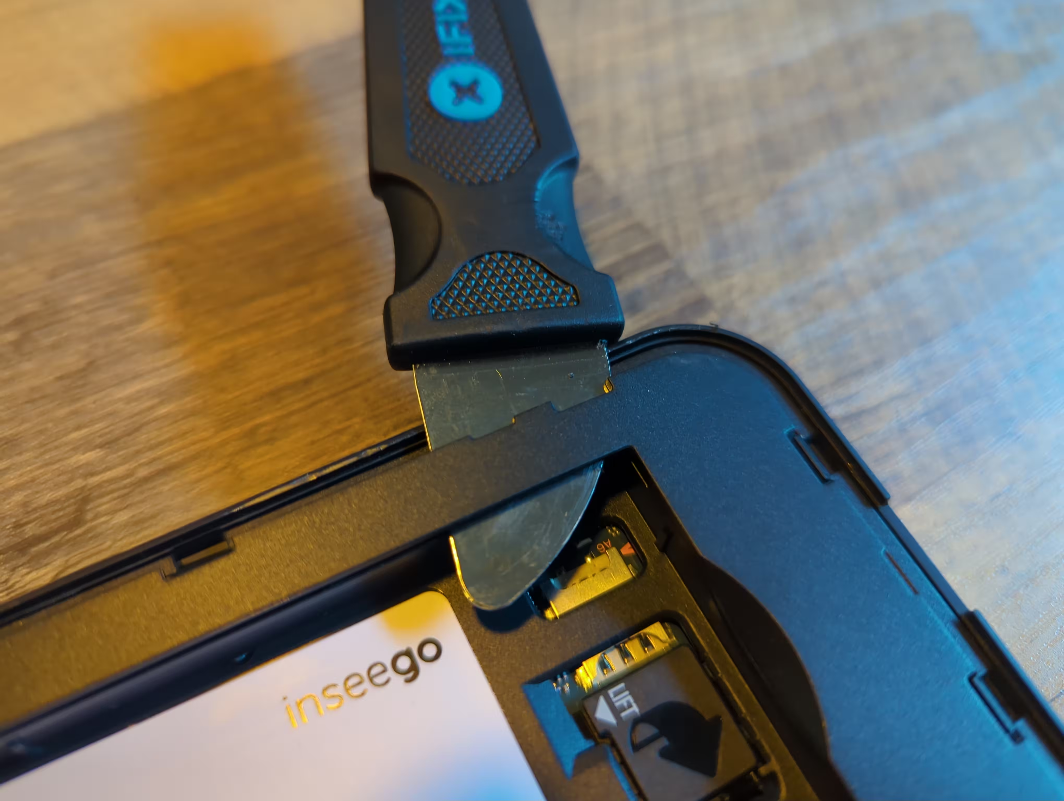
Step 1, use a spade to get in between the outer plastic cover to reveal the six Torx TR6 screws underneath.

Step 2. Find the 6 Torx TR6 screw holes. One in each corner and two in the middle. Remove the screws.
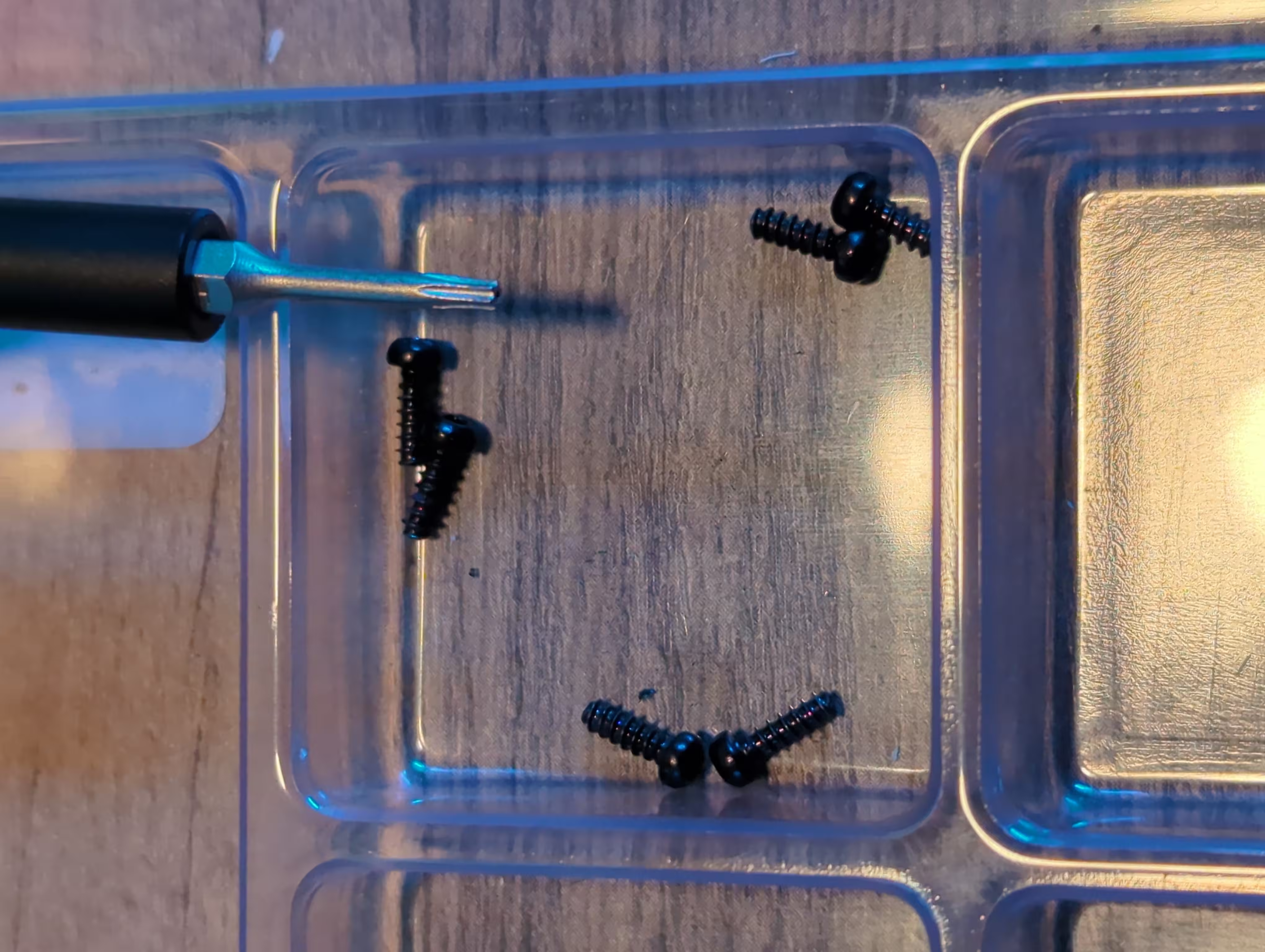
Step 4. The 6 Torx TR6 screws are all the same. Store them somewhere safe.
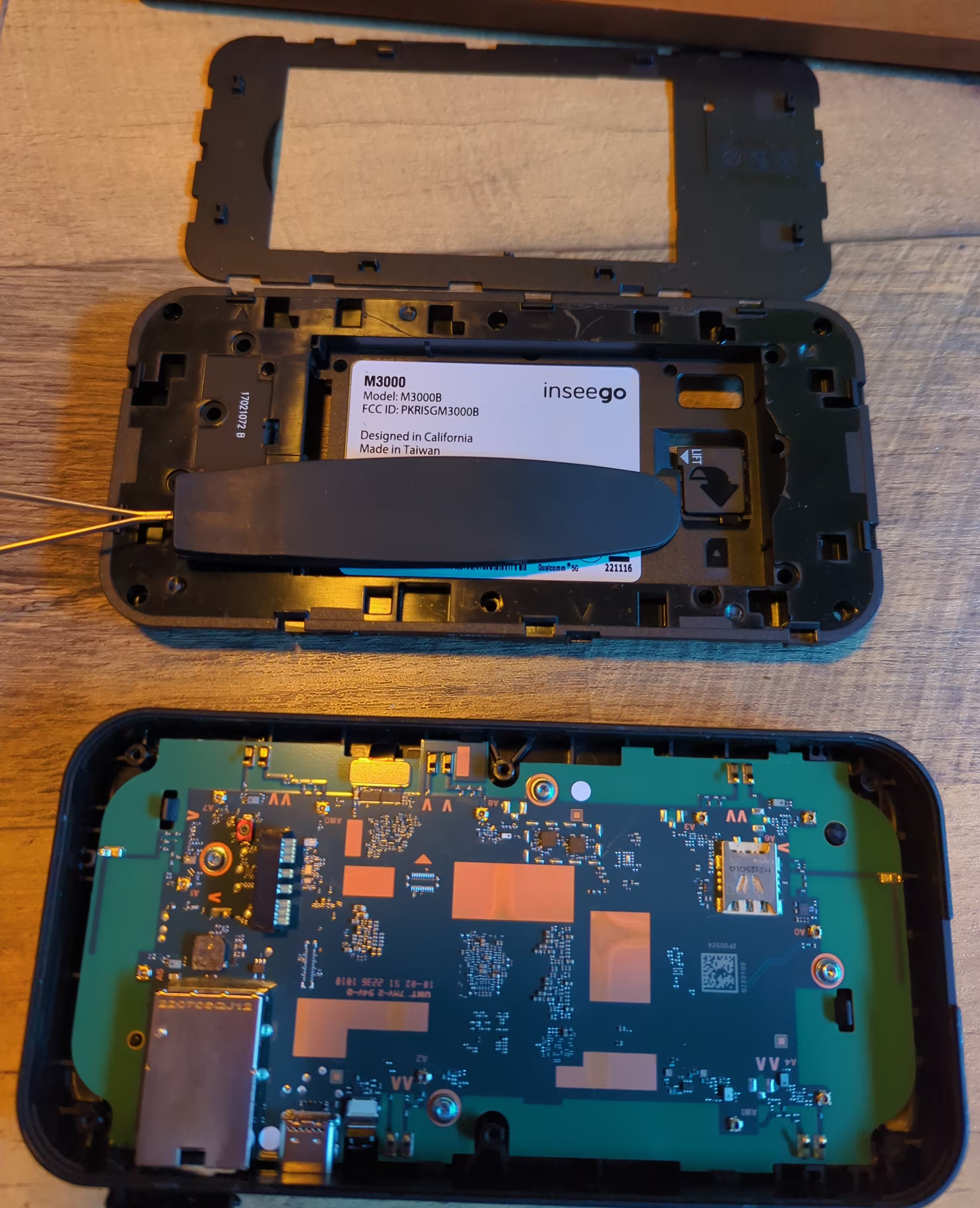
Step 5. Using a stiff metal tool, like a small flat head screwdriver, carefully pry the black plastic out of the external case. If you look carefully, there are two arrows guiding you where to gently pry. The arrows are located in the upper left and just to the right of the middle of the plastic piece (see above).
Step 6. There are 4 Torx TR6 silver screws surrounded by metal rings. Remove them. you then have to carefully pop the two plastic holders (at around 10:00 and 16:00 if this were a clock face) to lift the circuit board. Underneath the circuit board is a metal shield. As you loosen the circuit board, you'll hear the shield rattle. This is a good sign. The circuit board is connected to the screen on the external case by two ribbon cables. These cables are opposite one another on the board. See the big RJ45 connector, to left is the USB-C connector, and then to the left is the first ribbon cable. Directly below that cable on the opposite side of the board is the other ribbon cable. Both cables appear to be stamped into place, so removal may DESTROY the cable.
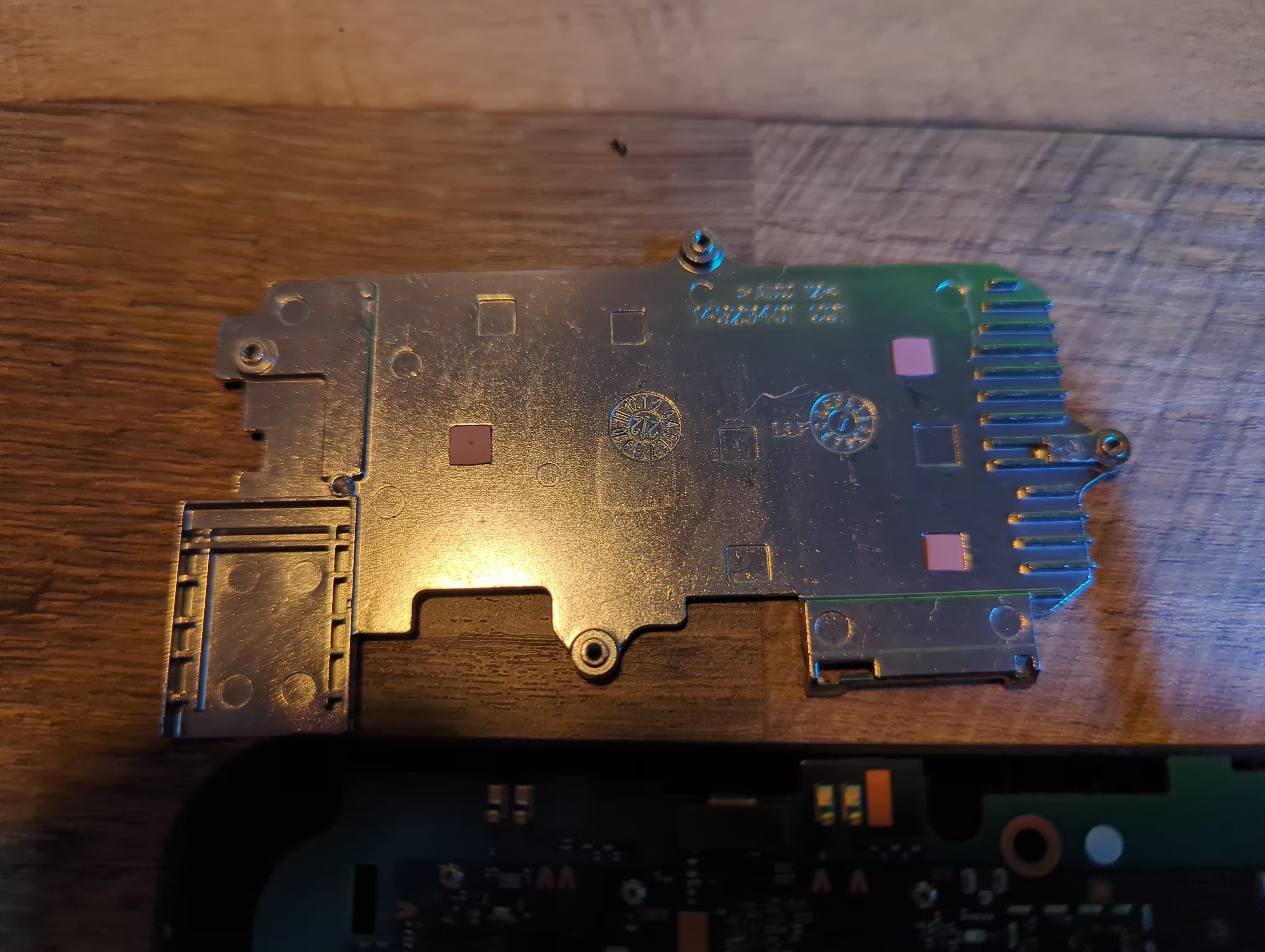
Step 8. Carefully rotate the metal shroud around the attached ribbon cables. See the shroud above. In the picture, the lower left corner is the RJ45 connector cover.
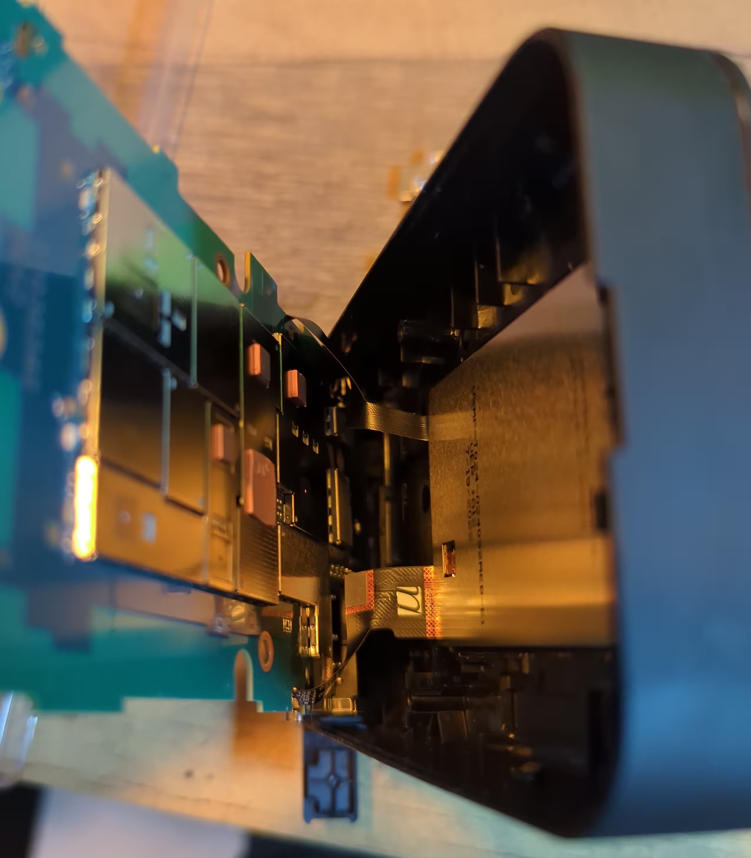
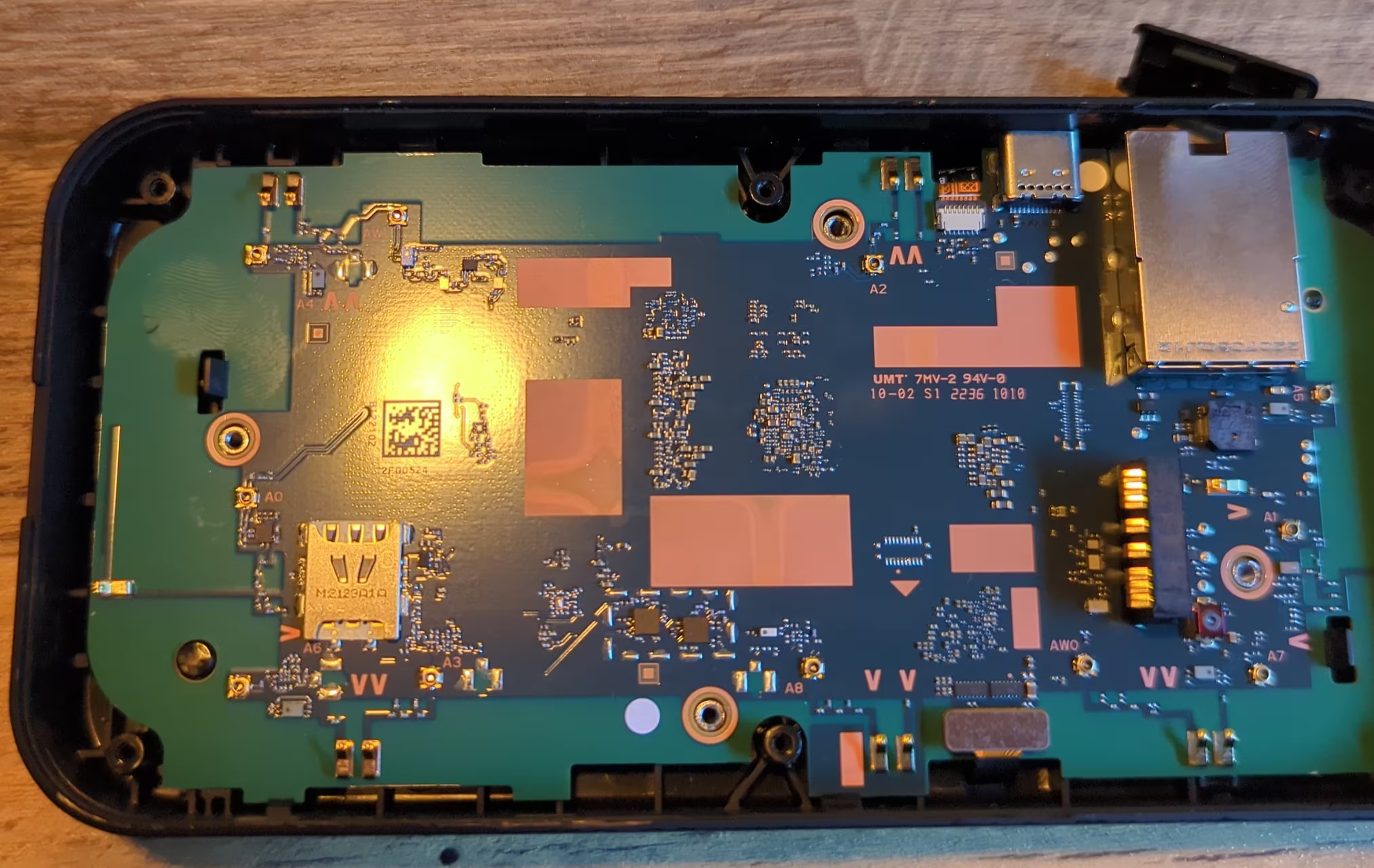
Step 9. This is the chip side of the circuit board (left side in picture) and the shield for the touch screen (right side in picture) in the external case. You are done at this point.
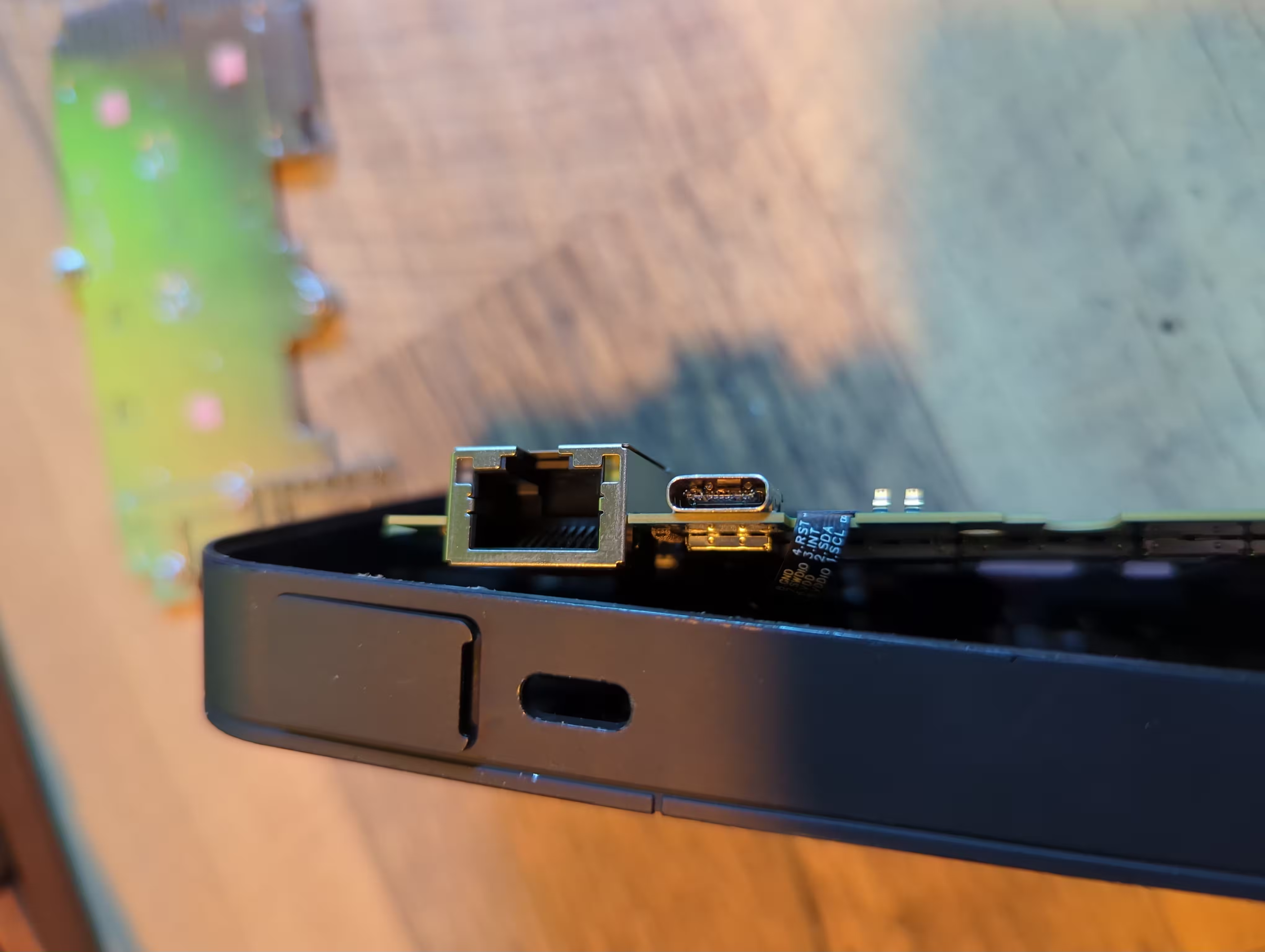
As a close-up, the left is the RJ45 connector for Ethernet. The right is the broke n USB-C receptacle. If you zoom in and look closely, the circuit board in the middle is cracked and misaligned. It appears the electrode broke because even with a meter I cannot get connectivity to the correct pin on the back of the connector. A $4 broken part makes the entire device useless. The $4 cost is based on pricing at Mouser Electronics (see link in last sentence). I'm sure Inseego gets them for less than $2 in bulk.
The full gallery of images is available.
